Documentation

ShapeBuilder V3 reference.

A practical guide for installing ShapeBuilder, editing splines, generating meshes, importing SVG-like shapes, placing prefabs, and checking UV output inside Unity.

ShapeBuilder V3 documentation overview

Setup

Getting Started

After importing ShapeBuilder, the fastest way to start is to use the ready-made prefabs included in the package. They give you a clean starting point for each main feature, without having to manually add every component yourself.
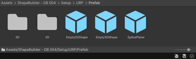
ShapeBuilder URP prefab folder in Unity
In an URP project, open Assets/ShapeBuilder - DB 004/Setup/URP/Prefab.

Prefab folders

The Prefab folder contains two example folders and three empty starter prefabs. Use the empty prefabs when you want to create your own object from scratch, and use the example folders when you want to inspect how existing objects are built.

2D Examples made with Shape2DGraphSpline.
3D Examples made with OutlineBezierShape.
Empty2DShape.prefab Default prefab for creating a new Shape2DGraphSpline.
Empty3DShape.prefab Default prefab for creating a new OutlineBezierShape.
SplinePlacer.prefab Default prefab for placing repeated objects along a spline.
  1. Import the ShapeBuilder package into your Unity project.
  2. Open Assets/ShapeBuilder - DB 004/Setup/URP/Prefab.
  3. Drag one of the starter prefabs into the scene.
  4. Edit the anchors, paths, profile settings, or placement settings depending on the component.
  5. Use Refresh Mesh when you want to rebuild the generated result.

Render pipeline and default materials

ShapeBuilder is designed mainly for URP, and the included demo prefabs and examples are prepared for URP projects. The tool can still be used with other Unity render pipelines, but materials may need to be assigned again on each generated GameObject.

URP The package includes URP-ready materials. When a component is added with Add Component, or when the component is reset, ShapeBuilder tries to assign ShapeBuilder/DefaultMaterialURP automatically.
Built-in In the Built-in Render Pipeline, ShapeBuilder tries to assign ShapeBuilder/DefaultMaterialBuildIn when the component is added or reset. If it cannot find it, it falls back to Unity's Standard shader.
HDRP HDRP is supported as generated mesh data, but materials must be assigned manually. Use HDRP-compatible materials on the MeshRenderer of each ShapeBuilder object.
Automatic material detection only runs when the component is created with Add Component or when the component is reset. Existing prefabs or copied objects keep their current MeshRenderer material.

Demo scenes

The package also includes demo scenes that show how the tools are meant to be used together. They are useful for learning the workflow before building your own shapes.
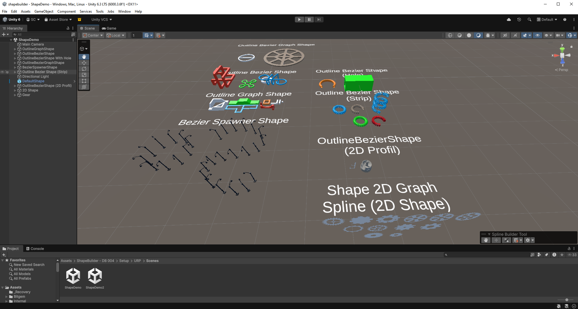
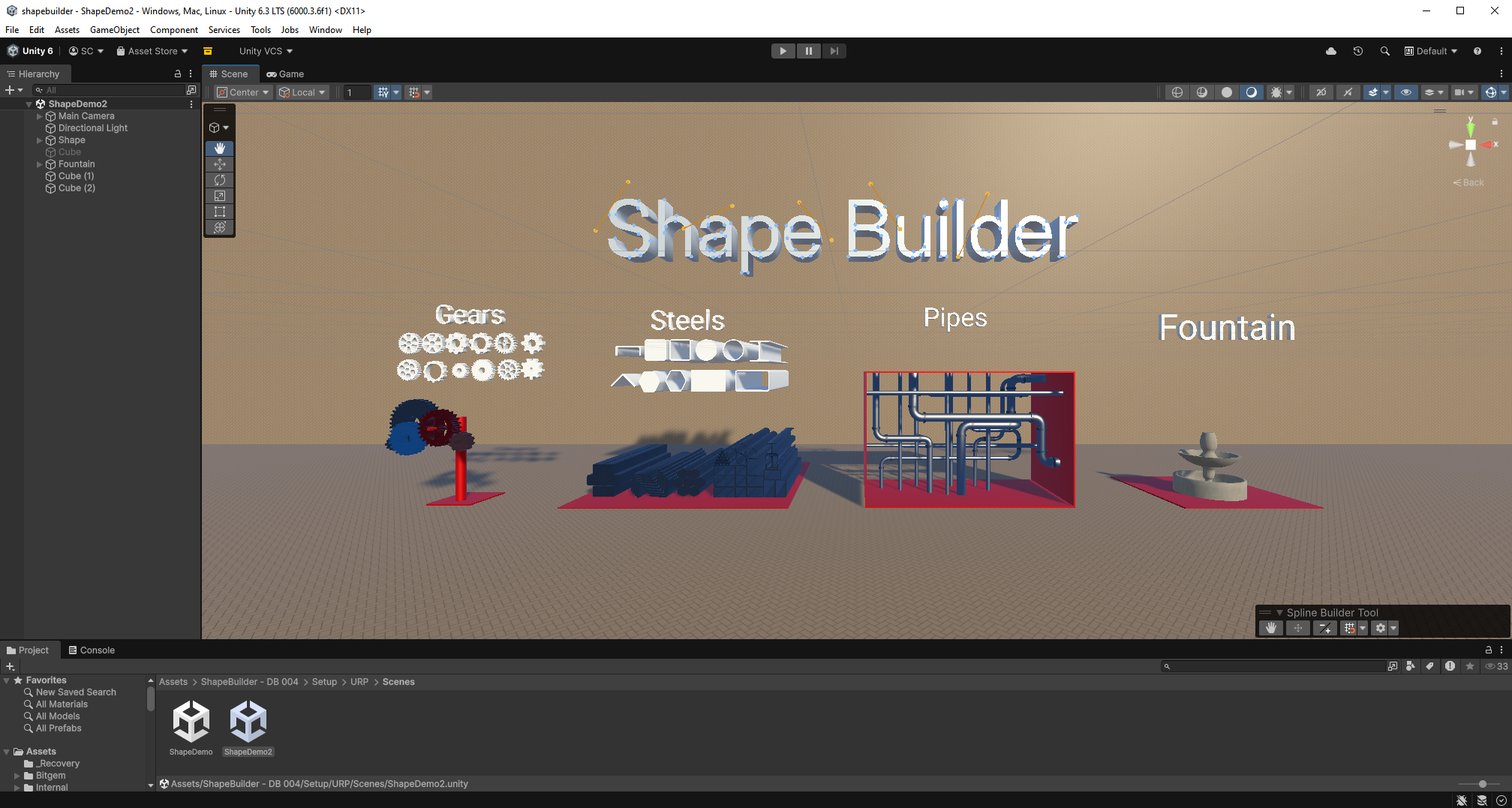
ShapeDemo scene showing generated shapes and SplinePlacer examples
ShapeDemo Shows several generated shapes and SplinePlacer examples.
ShapeDemo2 scene showing extruded shapes using 2D base profiles
ShapeDemo2 Focuses on shapes generated by extrusion using 2D base profiles.

Overview

Core Concepts

ShapeBuilder is built around editable construction data. The goal is to create meshes and object layouts inside Unity while keeping the source information available: anchors, paths, Bezier splines, profiles, resolution settings, fill rules, and UV data.

The generated mesh is the output. The editable shape, spline, or placement setup is the source.
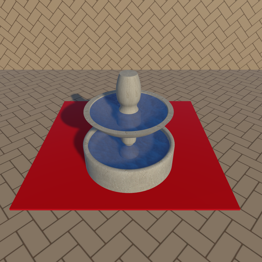
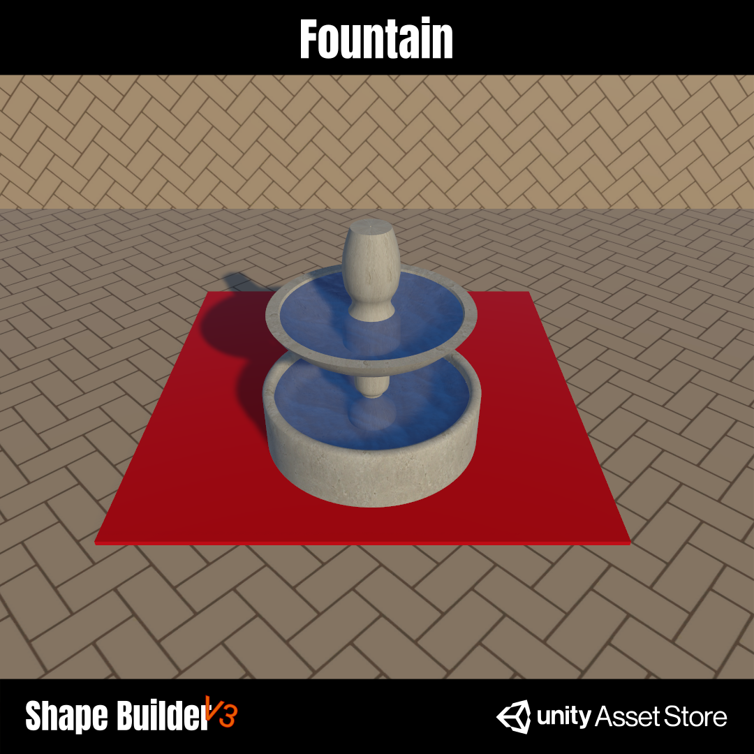
Fountain generated with OutlineBezierShape

OutlineBezierShape

Generates 3D meshes by extruding a 2D profile along a Bezier spline. It is used for pipes, roads, fountains, rails, frames, strips, and any object that starts from a section and follows a path.

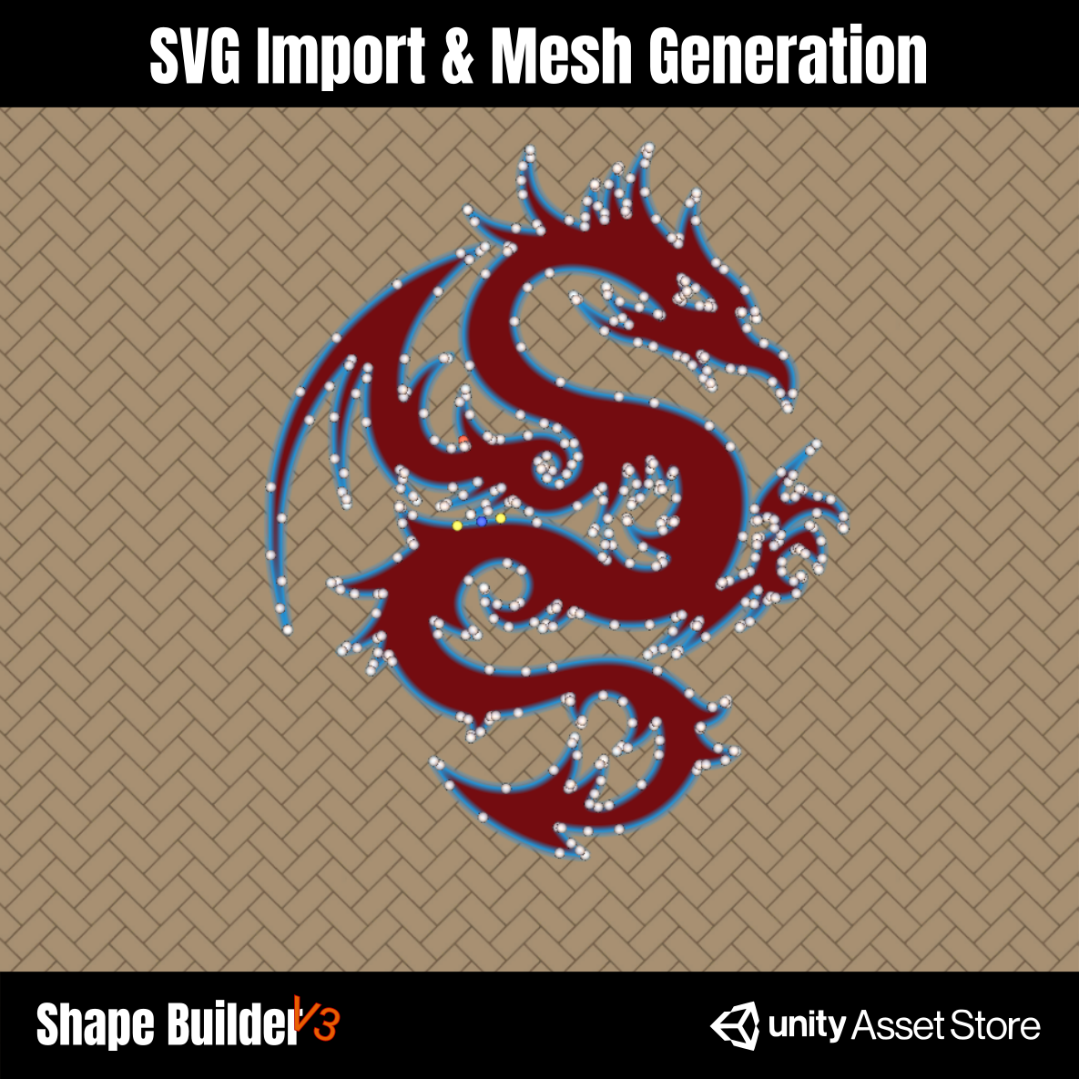
Dragon generated with Shape2DGraphSpline

Shape2DGraphSpline

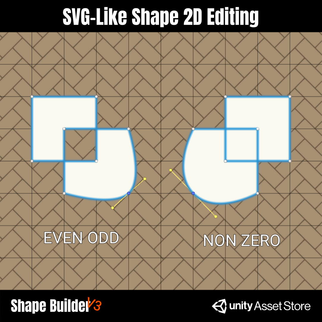
Generates filled 2D meshes from editable graph paths. It supports exterior and interior contours, holes, intersections, and SVG-like fill rules such as Even Odd and Non Zero.

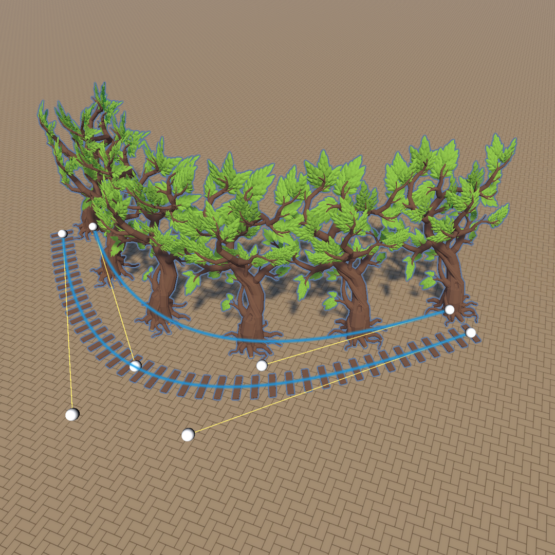
Objects placed along a spline with SplinePlacer

SplinePlacer

Places repeated prefabs along a Bezier spline. It is used when the goal is not only mesh generation, but also controlled object placement along a designed path.

Editable source

Each tool keeps its source data editable so the result can be adjusted without rebuilding from scratch.

Generated output

The output can be a 2D mesh, a 3D extrusion, or a set of placed prefab instances.

Unity workflow

Most settings are controlled from the Inspector and can be refreshed during iteration.

Path Editing

Spline Builder Toolbar

The Spline Builder Toolbar is the main editing interface used by ShapeBuilder. It lets you edit the Bezier paths used to build 3D shapes with OutlineBezierShape, 2D graph shapes with Shape2DGraphSpline, and prefab placement with SplinePlacer. The editing workflow is similar between components, but some behavior changes depending on the selected tool.

Open the Spline Builder Tool overlay

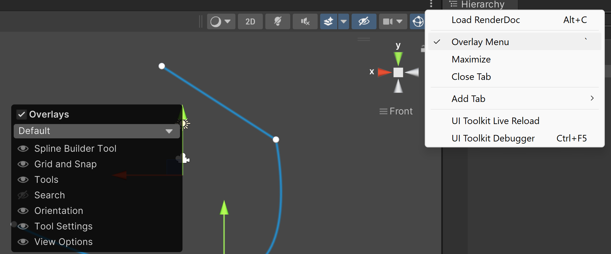
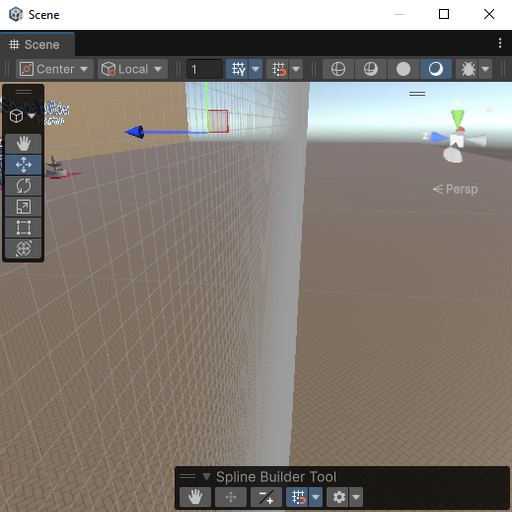
In the Unity Scene view, open the Overlays menu, then enable Spline Builder Tool. The toolbar appears directly inside the Scene view and exposes the editing modes used by ShapeBuilder.

Unity overlay menu showing the Spline Builder Tool overlay
Enable the Spline Builder Tool overlay from the Scene view overlay menu.

Toolbar modes

The toolbar is used to inspect the spline, move anchors, add or delete points, display the local grid, edit selected-anchor parameters, and change tangent mode.

Spline Builder toolbar with numbered buttons
The numbered toolbar buttons map to the editing modes below.
1. Hand Tool View spline connections without moving or editing anchors.
2. Move Anchor Drag anchors in the Scene view. On some components, selecting an anchor also exposes its parameters.
3. Add / Delete Point Left click to add a new point. To delete a point, hover an anchor and right click.
4. Display Grid Show or hide the local construction grid used for snapping anchor movement.
5. Parameters Open settings for the selected anchor and the toolbar/grid options.
6. Mirror & Equal Tangents Tangents are mirrored and keep the same length.
7. No Tangent The anchor has no tangent and creates a linear transition.
8. Mirror Only Tangents Tangents share a mirrored direction but can have different lengths.
9. Manual Tangents Tangents are fully independent and can be adjusted manually.

Editing anchors and tangents

Use the Move Anchor mode to move existing anchors. Use Add / Delete Point mode to insert or remove points. For a standard Bezier spline used by OutlineBezierShape, tangent mode is changed by switching to Move Anchor mode and double-clicking the anchor you want to edit.

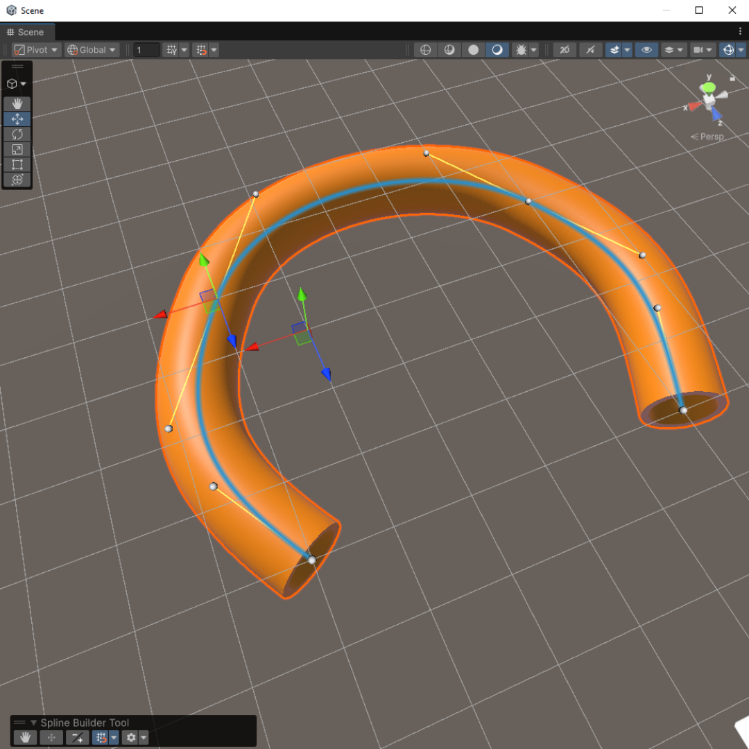
Bezier spline editor with anchors and tangents visible
Bezier anchors and tangents are edited directly in the Scene view.
In Add / Delete Point mode, left click adds a point. Hover an existing anchor and right click to delete it.

Toolbar parameters

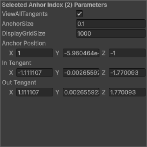
The parameter menu gives access to the selected anchor transform and tangent values. It is useful when an anchor needs a precise position instead of a manual Scene view drag.

Spline Builder selected anchor parameters
Selected-anchor parameters can be edited numerically from the toolbar menu.

Local grid and snapping

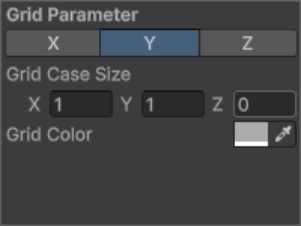
The grid is local to the selected object. Its position and rotation follow the selected object transform, and anchors snap to the configured grid cells when the grid is enabled. The grid parameters control the axis, color, and cell size.

Spline Builder grid parameters
Grid settings control the axis, color, and cell size used for anchor snapping.
Local grid displayed on the X axis
X axis gridGrid view aligned to the local X axis.
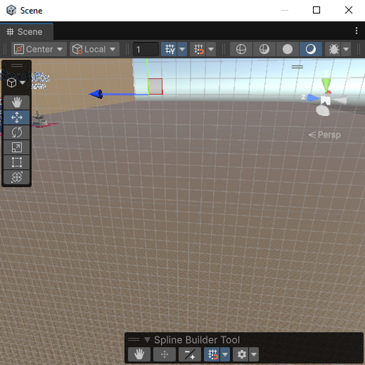
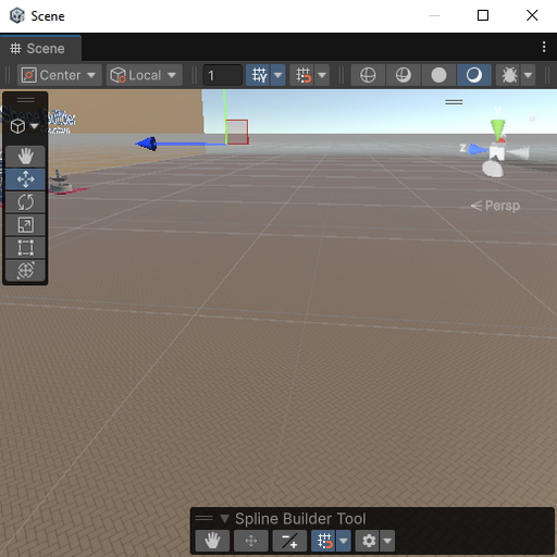
Local grid displayed on the Y axis
Y axis gridGrid view aligned to the local Y axis.
Local grid displayed on the Z axis
Z axis gridGrid view aligned to the local Z axis.

Component-specific behavior

OutlineBezierShape Uses a 3D Bezier spline for extrusion. The grid is local to the selected object. Dragging an anchor with the grid enabled snaps it to the grid. To freely position or edit a selected anchor, use Move Anchor mode and double-click the anchor first.
Shape2DGraphSpline Works with paths. In Add / Delete Point mode, left click continues the current path by adding points. Right click in empty space cancels the current path. Paths are looped automatically. Anchors are defined in 2D, so the grid uses the object's Z plane with configurable X and Y cell size.
SplinePlacer Uses a Bezier spline as the placement path. Its transform and grid behavior are close to OutlineBezierShape, but the output is a set of placed prefab instances instead of a generated mesh.

Transform notes

For OutlineBezierShape and SplinePlacer, the grid follows the selected object's local transform. For Shape2DGraphSpline, anchors are edited in two dimensions: object scale and Z rotation affect the anchors and tangents, while X and Y rotation do not change the 2D editing plane. The generated mesh is still oriented by the GameObject transform.

For 3D splines, edit anchors in the selected object's local space. The local grid helps keep points aligned while building paths for extrusion or prefab placement.

2D Meshes

Shape2DGraphSpline

Shape2DGraphSpline creates editable filled 2D meshes from graph paths. The workflow is close to SVG editing: you create exterior paths, optional interior paths, resolve the graph, then build a Unity mesh from the filled loops.

  • Path-based construction with exterior and interior contours.
  • Anchor, tangent, and link editing through the Spline Builder Toolbar.
  • Intersection and loop resolution before mesh generation.
  • Even Odd and Non Zero fill rules for holes and overlapping paths.
  • Can be used directly as a custom 2D profile for OutlineBezierShape.
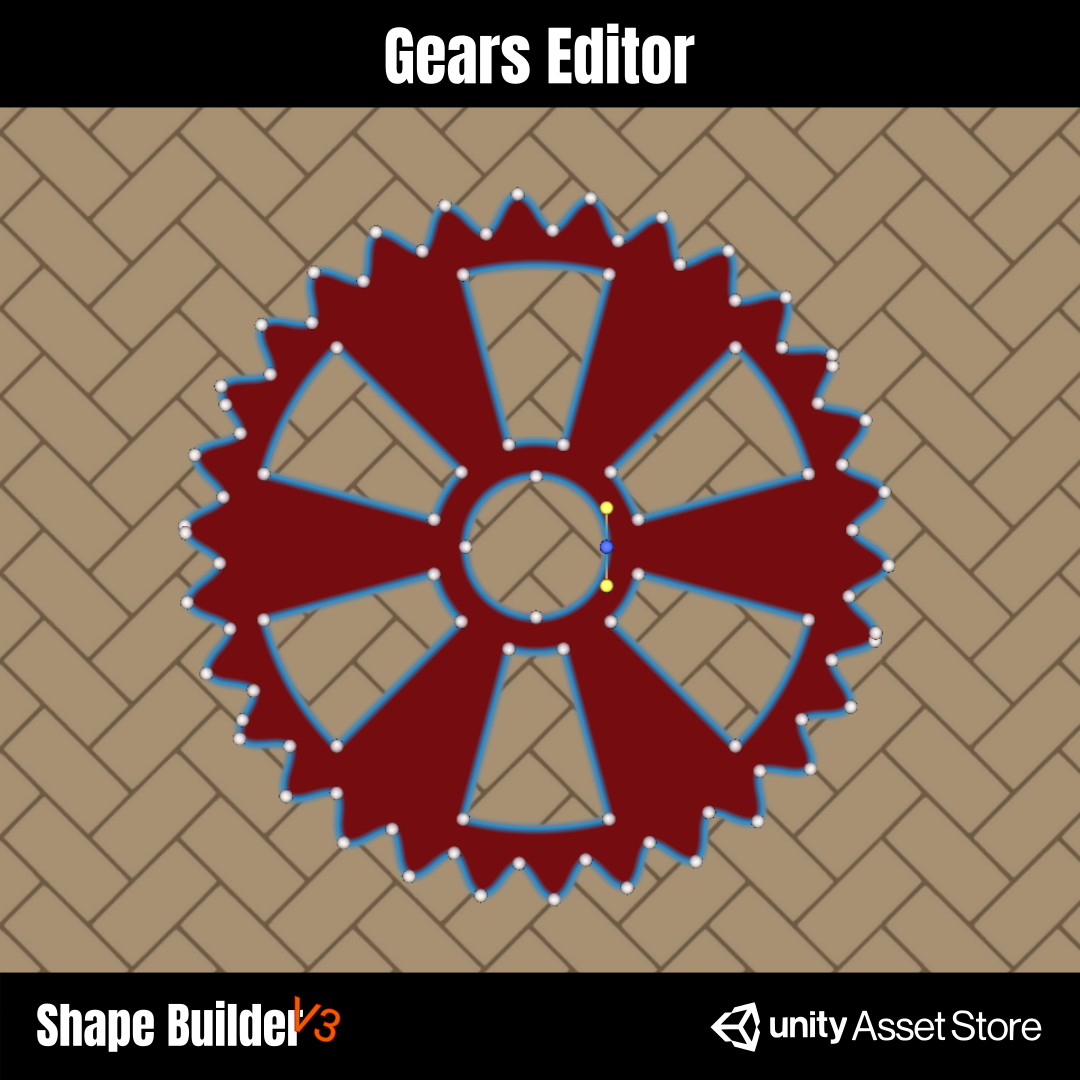
SVG-like Shape2DGraphSpline editing Gear editor with anchors and tangents SVG mesh importation converted to Shape2DGraphSpline

Adding paths

To draw a path, select the object, enable Add / Delete Point in the Spline Builder Toolbar, then left-click in the Scene view. The first click starts a new path, and each following left-click adds a new anchor to the current path. To stop the current path without adding another point, right-click in empty space.

Shape2DGraphSpline paths are looped automatically. In Non Zero mode, path direction matters: an inner path usually needs the opposite winding direction from the exterior path to behave like a hole.

Component fields

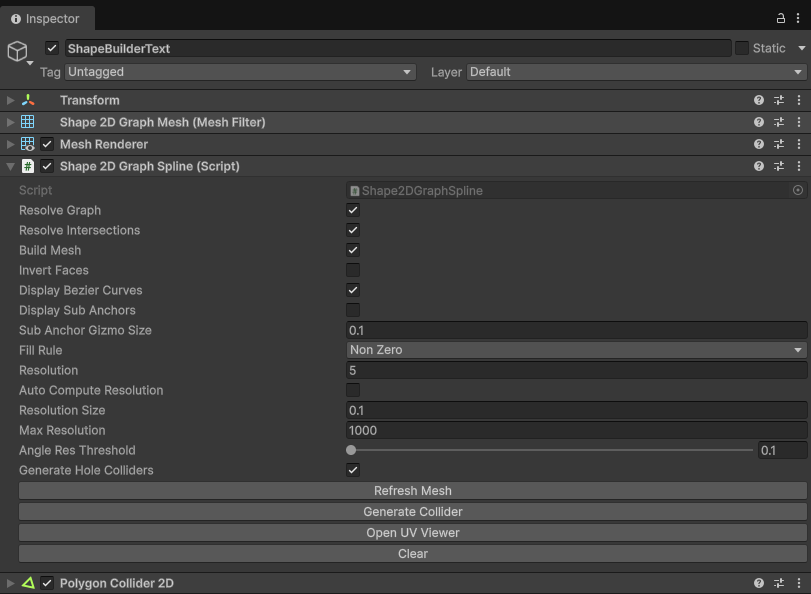
The component exposes the steps used to turn editable paths into a Unity mesh. These options control what Refresh Mesh recomputes, how curves are subdivided, how filled areas are detected, and what helper data is displayed in the Scene view.

Shape2DGraphSpline component fields in the Unity Inspector
Shape2DGraphSpline component with graph, fill, resolution, and display settings.
Resolve Graph Rebuilds the derived graph from the source paths. This includes curve subdivision and loop detection.
Resolve Intersections Splits and resolves crossing segments before triangulation. Enable it for final or complex shapes.
Build Mesh Generates the Unity mesh from the resolved filled loops. Disable it while editing very large shapes.
Invert Faces Flips the generated face orientation when the mesh needs the opposite visible side.
Display Bezier Curves Shows the editable source curves in the Scene view, useful while placing anchors and tangents.
Display Sub Anchors Shows generated internal anchors after subdivision. Useful for debugging, but heavier on large shapes.
Sub Anchor Gizmo Size Controls the display size of generated sub-anchor gizmos in the Scene view.
Fill Rule Non Zero uses path winding direction. Even Odd alternates filled and empty regions by nesting.
Resolution Fixed curve subdivision value used when Auto Compute Resolution is disabled.
Auto Compute Resolution Computes curve resolution automatically from the target segment size instead of using one fixed value everywhere.
Resolution Size Target size used by automatic resolution to estimate how many segments are needed along curves.
Max Resolution Upper limit used to prevent automatic resolution from generating too many subdivisions.
Angle Res Threshold Helps decide where additional curve detail is useful based on angle changes.
Refresh Mesh Rebuilds the result using the options currently enabled on the component.
Generate Hole Colliders When enabled, generated 2D colliders keep inner contours as holes instead of filling every loop as solid collision.
Generate Collider Creates or updates the generated PolygonCollider2D from the current 2D graph mesh result.
Open UV Viewer Opens the 2D UV viewer for inspecting and exporting the generated UV layout.
Clear Clears the current Shape2DGraphSpline data when you want to restart from an empty shape.

Editing and refresh workflows

The graph toggles can be used like draft and final modes. Disable expensive work while editing, then enable the full pipeline when you need the accurate final mesh.

Fast anchor editing OnDisplay Bezier Curves OffResolve Graph, Resolve Intersections, Build Mesh, Display Sub Anchors Best for moving anchors and tangents on large shapes without recalculating the mesh.
Spline preview only OnDisplay Bezier Curves OffResolve Graph, Resolve Intersections, Build Mesh, Display Sub Anchors Shows the source curves only, useful when placing paths cleanly.
Fast mesh preview OnResolve Graph, Build Mesh OffResolve Intersections, Display Sub Anchors Good for clean paths, holes, and separate contours without self-intersections.
Final accurate result OnResolve Graph, Resolve Intersections, Build Mesh OptionalDisplay Bezier Curves, Display Sub Anchors Use this before validating the final mesh output.
Internal graph debug OnResolve Graph, Display Sub Anchors OptionalDisplay Bezier Curves, Build Mesh Useful to inspect generated subdivision anchors. Avoid it on large shapes during normal editing.

SVG import

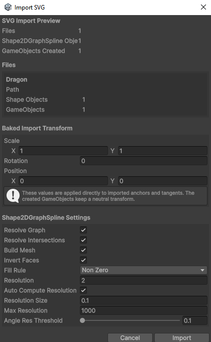
ShapeBuilder V3 can import SVG files as editable Shape2DGraphSpline objects. Use GameObject > ShapeBuilder > Import SVG as Shape2DGraphSpline, then select one or more SVG files from the file explorer.

Before importing, the menu lets you preconfigure the component settings and the transform that will be applied to the created GameObjects. The confirmation step also indicates how many GameObjects will be created.

Unity menu for importing SVG as Shape2DGraphSpline
Import SVG files from the Unity ShapeBuilder menu, then edit the generated paths in Unity.

UV mapping

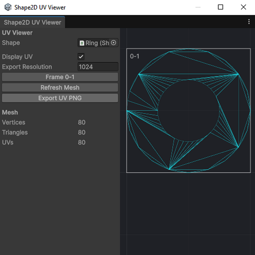
The UV mapping view displays the generated 2D UV layout. It can be used to inspect the mesh mapping, export the UV preview as a PNG, and choose a target resolution for the export. This gives you a clean support image when you want to paint or prepare textures for a generated shape.

Shape2DGraphSpline UV mapping window
The UV mapping view can export a PNG reference for texturing generated 2D meshes.

Finalizing a mesh

For the most accurate result, enable Resolve Graph, Resolve Intersections, and Build Mesh, then press Refresh Mesh if the mesh does not update automatically. Refresh uses the options currently enabled on the component, so disabled steps are intentionally skipped.

If the graph display or mesh result looks temporarily broken while editing, pressing Refresh Mesh can rebuild the derived graph and recover the preview.

3D Generation

OutlineBezierShape

OutlineBezierShape starts from a 2D base profile and extrudes it along a Bezier spline. The profile can be generated directly by the component, or assigned from a Shape2DGraphSpline when you need a custom section.

  • Round, polygonal, hollow, and custom profiles.
  • Regular convex polygon profiles with optional holes.
  • Custom 2D profiles using Shape2DGraphSpline.
  • Caps, side surfaces, strips, curved borders, and smoothing controls.
  • UV settings for side, cap, loop, linear, and planar regions.
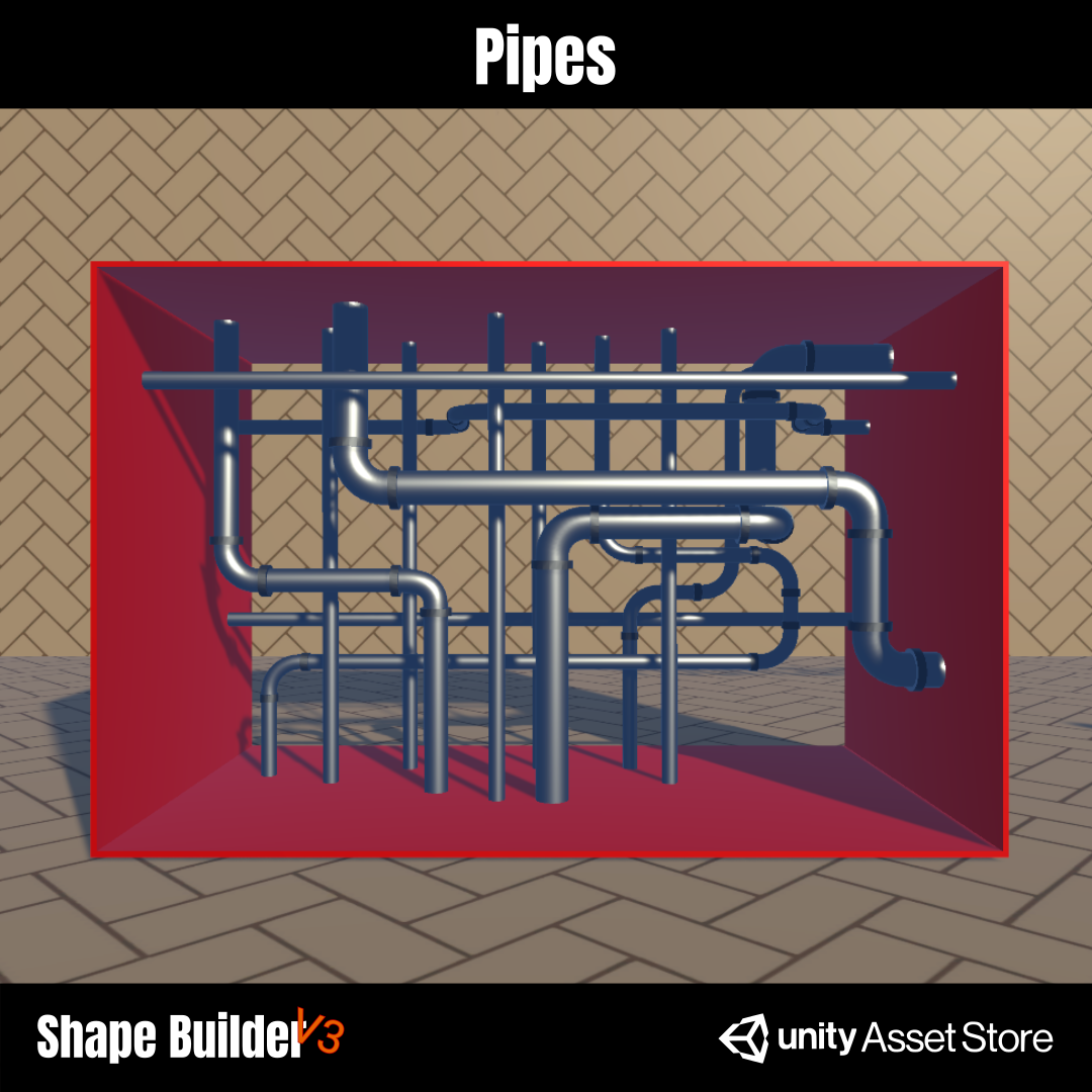
Fountain made with OutlineBezierShape Pipes made with OutlineBezierShape Road editor made with OutlineBezierShape
When you add OutlineBezierShape, a BezierSpline component is added automatically. Add and edit anchors with the Spline Builder Toolbar. To close the extrusion path, enable Is Looped on the BezierSpline component.

Component layout

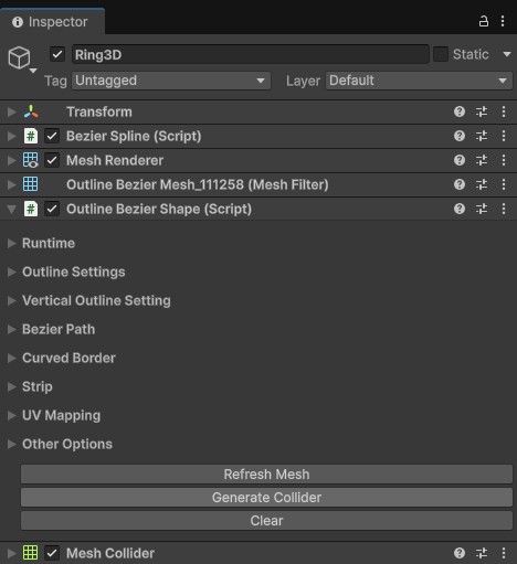
The component is organized into foldout sections. Each section controls one part of the generation pipeline: runtime refresh, profile generation, custom profile assignment, spline sampling, border treatment, strips, UVs, and final debug options.

OutlineBezierShape component in the Unity Inspector
OutlineBezierShape Inspector with foldout sections for generation and UV settings.

Runtime

Runtime options control when the generated mesh is rebuilt.

OutlineBezierShape runtime options
Use automatic refresh while iterating, or disable it and rebuild manually on heavier meshes.
Auto Generate On Change When enabled, the mesh rebuilds automatically when settings change. Disable it on heavy shapes and use Refresh Mesh manually.

Outline settings

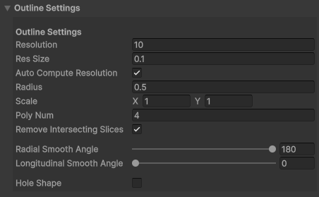
Outline settings define the generated 2D profile when no custom profile is used. This is where you configure the section radius, scale, polygon count, smoothing, and optional hole.

OutlineBezierShape outline settings
Generated profile settings for round, polygonal, scaled, or hollow sections.
Resolution Fixed subdivision count used for the generated profile when automatic resolution is disabled.
Res Size Target segment size used when automatic resolution is enabled. Smaller values create more detail.
Auto Compute Resolution Computes the profile resolution from Res Size instead of using the fixed resolution value.
Radius Base radius of the generated profile.
Scale 2D scale applied to the generated profile, useful for flattening or stretching the section.
Poly Num Number of sides for the generated polygon profile. For example, 4 creates a square-like section.
Remove Intersecting Slices Removes slices that intersect during generation, useful when the path bends tightly or folds back on itself.
Radial Smooth Angle Controls normal smoothing around the profile.
Longitudinal Smooth Angle Controls normal smoothing along the spline direction.
Hole Shape / Hole Size Turns the generated profile into a hollow section and controls the size of the inner hole.

Vertical custom profile

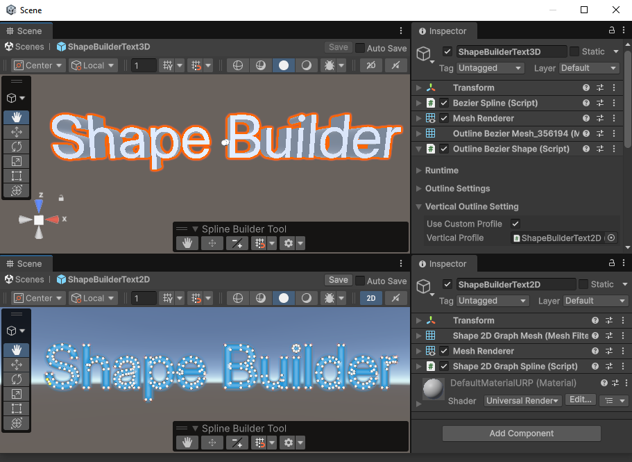
A custom profile lets the extrusion use a real editable 2D shape as its section instead of a generated polygon. This is useful for pipes, rails, borders, decorative molding, fountains, or any shape that needs a specific silhouette.

OutlineBezierShape custom vertical profile settings
Assign a Shape2DGraphSpline as the vertical profile when generated profiles are not enough.
Use Custom Profile Uses a referenced Shape2DGraphSpline as the extrusion section.
Vertical Profile Reference to the 2D graph shape used as the custom profile.

Bezier path

The Bezier path controls where the profile is extruded. Edit the path with the Spline Builder Toolbar. If the object should form a closed ring or loop, enable Is Looped on the BezierSpline component.

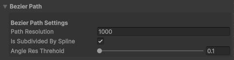
OutlineBezierShape Bezier path settings
Path settings control how the extrusion path is sampled.
Path Resolution Sampling precision used to evaluate the Bezier path and distribute points at more even distances. This is not the mesh profile resolution.
Is Subdivided By Spline Applies the configured outline resolution per Bezier spline segment instead of across the whole path. For example, with 4 spline segments and a fixed resolution of 10, the path is built with 4 x 10 subdivisions.
Angle Res Threshold Angle threshold used to decide where more subdivisions are needed along the path.

Curved border and strips

Curved border settings add rounded transitions on the profile edges. Strip settings can split the extrusion into separated bands instead of generating one continuous surface.

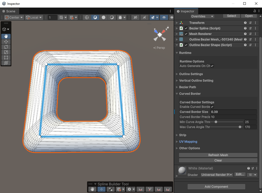
OutlineBezierShape curved border settings
Curved BorderEnable curved borders, set the border size, precision, and angle thresholds.
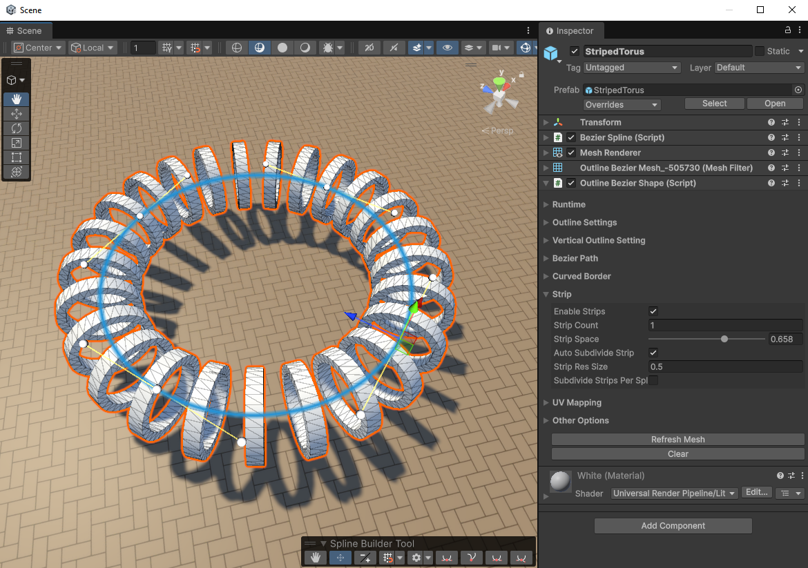
OutlineBezierShape strip settings
StripEnable strips, choose the strip count, spacing, and subdivision behavior.
Enable Curved Border Adds rounded border treatment to eligible edges of the profile.
Curved Border Size / Precision Controls the radius and subdivision count of the rounded border.
Min / Max Curve Angle Threshold Limits which angles receive the curved border treatment.
Enable Strips Generates separated bands instead of one continuous extrusion surface.
Strip Count / Strip Space Controls how many strips are generated and how much space is left between them.
Auto Subdivide Strip Computes strip subdivision automatically from the strip resolution settings.
Subdivide Strips Per Spline Lets strips follow the spline curvature more closely.

UV mapping

UV mapping controls how side faces, caps, and loops use the texture atlas. Use planar modes for projection-based mapping, or linear modes when the texture should follow the extrusion length.

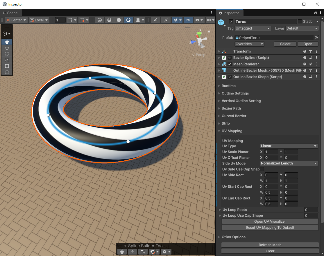
OutlineBezierShape UV mapping settings
UV mapping settings for side faces, caps, loop rects, and cap-shape based mapping.
UV Type Linear follows the profile and path length. YZ, XZ, and XY use planar projection.
Uv Scale / Offset Planar Controls repetition and offset in planar UV modes.
Side Uv Mode Tiled Length repeats by real spline length. Normalized Length stretches from 0 to 1.
Uv Side Use Cap Shape Uses the cap or profile shape to map side faces instead of a classic linear unwrap.
Uv Side Rect Atlas region used for side faces, defined as X, Y, W, H in UV 0-1 space.
Uv Start / End Cap Rect Atlas regions used by the start and end caps.
Uv Loop Rects Optional per-loop atlas rects. For example, use them to assign a different UV area to interior hole loops.
Uv Loop Use Cap Shape Per-loop option to use cap-shape based mapping for specific loops, such as selected interior holes.
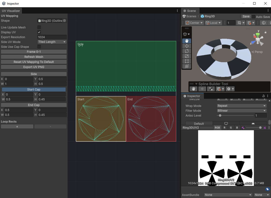
OutlineBezierShape UV viewer
The UV viewer shows the 0-1 atlas space, live mesh update options, UV rects, and PNG export.
The UV Visualizer can also be used for direct editing: drag the side, start cap, end cap, and custom loop zones by hand to adjust their atlas placement visually.

Other options and finalizing

Use Refresh Mesh to rebuild the mesh with the current settings. If the object is heavy, disable automatic generation while editing, then refresh manually when the profile, path, strips, and UVs are ready.

Start Rotation Offset Rotates the profile around the path when the section is generated correctly but starts with the wrong orientation.
Display Mesh Normals Displays generated normals for debugging lighting and smoothing issues.
Mesh Normal Display Size Controls the length of displayed normal lines.
Refresh Mesh Rebuilds the generated mesh from the current component settings.
Generate Collider Creates or updates a MeshCollider using the current generated OutlineBezierShape mesh.
Clear Clears the generated shape or mesh data when you need to restart.

Object Placement

SplinePlacer

SplinePlacer is used to place repeated prefabs along a Bezier spline. It is useful when placement matters as much as mesh generation: fences, lamps, rails, planks, trees, or modular scene details.

  • Assign a spline path and a prefab to repeat.
  • Choose the output container for generated instances.
  • Use resolution or distance settings to control placement density.
  • Optionally align objects to the spline tangent.
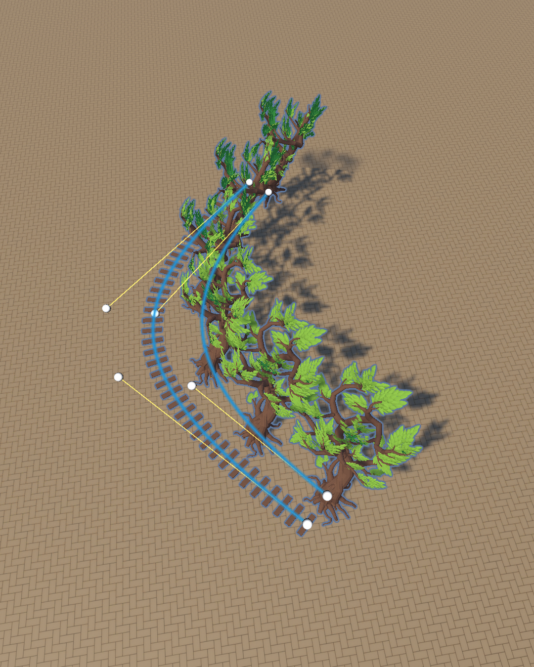
Tree and wood spline placement result
Repeated objects can follow the same editable spline path.
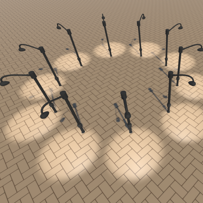
SplinePlacer result with repeated objects along a path
SplinePlacer can distribute a chosen prefab along a designed Bezier path.

Component fields

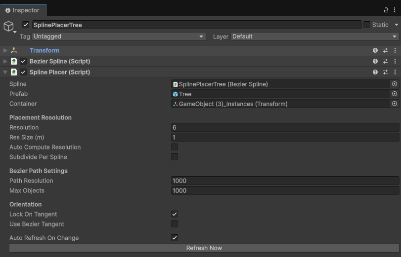
The component takes a spline, a prefab, and a container, then generates repeated instances along the path according to the placement and orientation settings.

SplinePlacer component in the Unity Inspector
SplinePlacer component with spline, prefab, placement resolution, path, orientation, and refresh settings.
Spline Bezier spline used as the placement path. Edit it with the Spline Builder Toolbar.
Prefab Prefab instantiated repeatedly along the spline.
Container Transform that receives the generated instances, keeping the hierarchy clean.
Resolution Fixed number of placed objects when automatic resolution is disabled.
Res Size (m) Target spacing in meters when automatic resolution is enabled.
Auto Compute Resolution Computes the placement count from the spline length and Res Size (m).
Spawn By Distance Places objects every Res Size (m) exactly instead of distributing a computed count evenly.
Subdivide Per Spline Applies the placement resolution per spline segment instead of across the full path.
Path Resolution Sampling resolution used to evaluate the Bezier path length, positions, and tangents.
Max Objects Safety limit for the number of generated prefab instances.
Lock On Tangent Rotates placed objects so they follow the path direction.
Use Bezier Tangent Uses the evaluated Bezier tangent for orientation instead of a direction computed from neighboring samples.
Auto Refresh On Change Automatically refreshes placed instances when the spline or settings change.
Refresh Now Regenerates the placed instances manually using the current settings.

Typical workflow

  1. Create or assign a Bezier spline path.
  2. Assign the prefab you want to repeat.
  3. Choose the container that will hold generated instances.
  4. Set a fixed resolution, or enable automatic resolution and tune Res Size (m).
  5. Enable tangent alignment when the prefab should follow the curve direction.
  6. Use Refresh Now to rebuild the placed objects.

Import

SVG Import

ShapeBuilder V3 can import SVG files as editable Shape2DGraphSpline objects. Use GameObject > ShapeBuilder > Import SVG as Shape2DGraphSpline, then select one or more SVG files from the file explorer.

Before importing, the menu lets you preconfigure the component settings and the transform that will be applied to the created GameObjects. The confirmation step also indicates how many GameObjects will be created.

Unity menu for importing SVG as Shape2DGraphSpline
Import SVG files from the Unity ShapeBuilder menu, then edit the generated paths in Unity.

Texturing

UV Mapping

ShapeBuilder keeps UV mapping as part of the generated mesh workflow. The goal is to make generated shapes usable with real materials, texture atlases, and paint references instead of producing geometry with unpredictable UVs.

Shape2DGraphSpline UV mapping

For 2D graph shapes, the UV mapping view displays the generated 2D UV layout. It can be used to inspect the mesh mapping, export the UV preview as a PNG, and choose a target resolution for the export. This gives you a clean support image when you want to paint or prepare textures for a generated 2D shape.

Shape2DGraphSpline UV mapping window
The Shape2DGraphSpline UV mapping view can export a PNG reference for texturing generated 2D meshes.

OutlineBezierShape UV mapping

For extruded shapes, UV mapping controls how side faces, caps, and loops use the texture atlas. Use planar modes for projection-based mapping, or linear modes when the texture should follow the extrusion length.

OutlineBezierShape UV mapping settings
UV mapping settings for side faces, caps, loop rects, and cap-shape based mapping.
UV Type Linear follows the profile and path length. YZ, XZ, and XY use planar projection.
Side Uv Mode Tiled Length repeats by real spline length. Normalized Length stretches from 0 to 1.
Side, cap, and loop rects Use atlas regions for side faces, start and end caps, and specific loops such as interior hole loops.
Cap-shape mapping Use the generated cap or profile shape as the UV basis for side faces or selected loops.

UV Visualizer

The UV Visualizer shows the 0-1 atlas space, live mesh update options, UV rects, and PNG export. For OutlineBezierShape, it can also be used for direct editing: drag the side, start cap, end cap, and custom loop zones by hand to adjust their atlas placement visually.

OutlineBezierShape UV visualizer
Use the visualizer to inspect and adjust cap, side, and custom loop UV regions.

Physics

Collisions

ShapeBuilder can generate collision components from the same mesh data used for the visual result. This is useful when a generated shape should also participate in Unity physics, selection volumes, triggers, or gameplay interactions.

Shape2DGraphSpline colliders

Shape2DGraphSpline generates 2D collision from the current graph result. Use Generate Collider after the graph and mesh settings are configured. The generated collider uses Unity's PolygonCollider2D.

Generate Hole Colliders Preserves holes from inner paths when creating the 2D collider. Disable it when you want simpler solid collision.
Generate Collider Creates or updates the PolygonCollider2D from the resolved 2D graph result.

OutlineBezierShape colliders

OutlineBezierShape generates 3D collision from the extruded mesh. Use Generate Collider after refreshing the mesh so the collider matches the current profile, path, caps, borders, strips, and UV-independent geometry.

Generate Collider Creates or updates a MeshCollider using the current generated mesh.
MeshCollider settings After generation, configure Unity's collider options normally, such as convex mode, trigger state, physics material, and layer overrides.

Recommended workflow

  1. Finish the visual mesh first with the correct graph, path, profile, and resolution settings.
  2. Press Refresh Mesh if the generated mesh is not already up to date.
  3. Press Generate Collider to build the collision component from the current result.
  4. Adjust Unity physics settings on the generated collider if the object needs trigger, convex, material, or layer behavior.
If the mesh changes later, regenerate the collider so physics stays aligned with the visible generated shape.

Code

API Examples

ShapeBuilder includes procedural examples for driving the components from code. These scripts are useful when you want to create generated shapes at edit time or runtime instead of manually editing every anchor in the Scene view.

GenerateTorus

GenerateTorus is a 3D generation example using OutlineBezierShape. It creates or reuses a child named Generated Torus, adds or retrieves OutlineBezierShape and BezierSpline, then builds a Bezier circle on the X/Z plane. The profile is extruded around that loop to produce a torus.

Horizontal Radius Main torus radius, from the center of the object to the center of the tube.
Vertical Radius Tube radius generated by OutlineBezierShape.
Horizontal Resolution Resolution used along the circular Bezier path.
Vertical Resolution Number of sides around the generated tube profile.
  1. EnsureShape() creates or retrieves the Generated Torus child.
  2. The BezierSpline is cleared with Clear() and set to Looped = true.
  3. Four anchors are added to form a circle, using the Bezier circle tangent factor 0.552284749831.
  4. OutlineBezierShape is configured with radius, resolution, polygon count, and smoothing.
  5. RefreshMesh() generates the final mesh once the data is ready.

GenerateRing

GenerateRing is a 2D generation example using Shape2DGraphSpline. It creates or reuses a child named Generated Ring, then generates two circular paths: one exterior path and one reversed interior path. With FillRule.NonZero, this produces a ring with a hole in the middle.

Horizontal Radius Outer radius of the ring.
Vertical Radius Inner radius of the ring, which controls the hole size.
Resolution Fixed resolution passed to Shape2DGraphSpline for the generated circular paths.
  1. EnsureShape() creates or retrieves the Generated Ring child.
  2. Expensive rebuild options are temporarily disabled: resolveGraph, resolveIntersections, and buildMesh.
  3. Clear() empties the shape, then CreatePathDeferred() creates the outer and inner paths.
  4. AddAnchorDeferred() adds circle anchors with ETangentMode.LINKED.
  5. The rebuild options are enabled again, then RefreshMesh() reconstructs the graph and mesh.

Recommended API workflow

Create or reuse components Use helper methods like EnsureShape() to create child objects and retrieve the required ShapeBuilder components.
Edit source data locally Clear and rebuild anchors, tangents, paths, profiles, and settings before asking the component to regenerate.
Avoid rebuilds during bulk edits Disable expensive graph and mesh options while adding many anchors, then re-enable them before the final refresh.
Refresh once at the end Call RefreshMesh() after all generated data has been configured.
Use Bezier circle tangents The classic factor 0.552284749831 creates clean circular curves with only four anchors.
Use GenerateTorus as the procedural example for OutlineBezierShape, and GenerateRing as the procedural example for Shape2DGraphSpline.

Help

Troubleshooting

The mesh does not update

Press Refresh Mesh or enable Auto Generate On Change if the component supports it.

The shape fills the wrong area

Try switching between Even Odd and Non Zero, then check the direction and nesting of paths.

The extrusion looks too low resolution

Increase the path or profile resolution until curves look smooth enough for the target asset.

The texture does not align

Open the UV visualizer and adjust the side, cap, or loop rects used by the generated mesh.